Directrices de diseño para la extrusión de plástico: qué son y por qué son importantes
Plastic extrusion design guidelines are the engineering rules that govern how a part’s cross-sectional geometry, material choice, wall thickness, and tolerance specifications should be set before a profile ever reaches the die. Follow them and you get consistent, cost-effective parts; ignore them and you spend months chasing warpage, dimensional drift, and scrap rates that kill your margin.
De un vistazo
- Process type: Continuous melt-and-form operation — raw pellets in, shaped profile out
- Die determines cross-section: Unlike injection molding, the die is fixed, so geometry errors are expensive to correct after tooling
- Wall thickness: Uniform walls are the single most important design rule; variations above roughly 25% of nominal wall thickness create differential shrinkage and warpage
- Tolerance class: Commercial extrusion tolerances typically run ±0.010 in.[5] to ±0.030 in.[6] on critical dimensions, depending on material and profile complexity
- Material drives everything: Melt viscosity, shrink rate, and thermal expansion differ dramatically across resin families — PVC, HDPE, ABS, and TPE all require distinct process windows
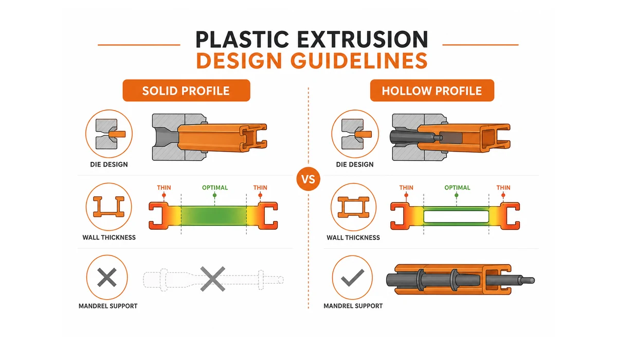
- Hollow vs. solid cross-sections: Hollow profiles require internal mandrel support in the die; solid profiles are simpler to tool but carry their own warpage risks
- Typical tooling lead time: 4–10 weeks for a new extrusion die in the United States
- Design-change cost leverage: Roughly 80% of a profile’s lifetime manufacturing cost is locked in at the design stage [1]
What plastic extrusion is — and what it is not
Plastic extrusion is a continuous manufacturing process in which thermoplastic material is melted, pressurized, and forced through a shaped die opening to produce a profile of uniform cross-section. The output can run in a continuous stream — pipe, tubing, sheet, wire insulation, window lineals, deck boards — and is cooled in a calibrated downstream line before being cut or coiled.
The process is often confused with injection molding, which produces discrete, three-dimensional parts by filling a closed cavity. Extrusion produces a constant cross-section that is theoretically infinite in length. If your part has a varying cross-section along its length — a boss on one end, a flange only in the middle — extrusion is the wrong process. That distinction matters before any design guidelines apply.
It is also distinct from blow molding (which forms hollow, enclosed shapes like bottles) and from compression molding. The design guidelines for plastic parts vary significantly across these processes; this reference covers extrusion specifically.
How the plastic extrusion process works
The core mechanism is straightforward. A screw rotates inside a heated barrel, conveying pellets from the hopper, melting them through a combination of barrel heat and frictional shear, then pushing the resulting melt at controlled pressure into a die.
The die is the profile-defining tool. Its opening mirrors the desired cross-section, though with deliberate drawdown compensation — the die opening is slightly larger than the finished part because the material shrinks as it cools. Getting that compensation factor right requires understanding a resin’s specific shrink rate, which is one reason material selection and die design are inseparable.
After the die, the extrudate passes through a sizing/calibration unit (a vacuum tank or dry calibration block that holds the shape while the outer skin solidifies), then through a water cooling trough, then a puller, and finally a cut-off saw or coiler. Every stage affects the final dimension. A puller speed set too fast stretches the profile and reduces wall thickness; too slow, and the profile sags.
📝 Nota: Shrink rate figures above represent typical midpoints from resin supplier datasheets; actual values vary with formulation, filler loading, and process conditions. Always confirm with your material supplier before committing die dimensions.
Comparing plastics: choosing the right resin for an extruded profile
The resin choice is the first design decision, and it forecloses options downstream. Here is how the four most common extrusion resins compare on the factors that matter most to U.S. designers and buyers:
| Resin | Melt Temp. Range (°F) | Typical Shrink (%) | Relative Die Cost | Key Strength | Key Limitation |
|---|---|---|---|---|---|
| Rigid PVC | 340–380 | 0.2–0.5 | Low–Medium | Excellent dimensional stability; low cost | Poor impact at low temperature; degrades if overheated |
| HDPE | 370–480 | 1.5–3.5 | Low | Chemical resistance; FDA food grades available | High shrink creates tighter tolerance demands |
| ABS | 400–450 | 0.4–0.8 | Medio | Surface finish; paintability | Moisture-sensitive; must be dried before processing |
| TPE/TPU | 360–430 | 1.0–2.5 | Medium–High | Flexibility; co-extrusion with rigid core | Requires precise temperature control; prone to melt fracture |
The practical rule: if your application is a rigid structural profile (window lineals, electrical conduit, deck trim), PVC or HDPE covers 90% of U.S. commercial extrusion. If you need flexibility or co-extrusion over a rigid substrate, TPE variants are the standard approach.
One point most extrusion design guide PDFs understate: filler loading changes the rules. HDPE filled with 40% calcium carbonate behaves almost like a different resin — shrink drops, stiffness rises, but the die land length must increase to maintain melt pressure. Always request the filled-compound datasheet, not just the base resin spec.
Solid shapes vs. hollow shapes: what the geometry demands
Solid profiles
Solid cross-sections — rods, flat strips, angle, channel, custom solid trim — are the simpler tooling case. The die has no internal mandrel, so there are no weld lines to manage.
The governing design tip for solid shapes is uniform wall thickness. When one section is significantly thicker than adjacent sections, that thick zone stays molten longer, shrinks more, and pulls neighboring material inward — creating bow, twist, or surface sink.
If your design requires a thick section (a reinforcing rib on a solid profile, for example), transition with a gradual taper rather than an abrupt step. A wall-to-wall ratio above 3:1 is where problems consistently appear. Staying at or below 2:1 is the safer design guideline for plastic parts.
Hollow profiles
Hollow profiles — pipe, tube, rectangular hollow sections, multi-cell window profiles — require a spider die o torpedo die that holds the internal mandrel in place with support legs. Those legs interrupt the melt flow, and where the split streams rejoin behind each leg, they form weld lines.
Weld lines are structurally weaker than the surrounding material — typically 60–90% of base tensile strength, depending on resin and processing conditions [2].
The design implication: keep weld lines out of high-stress zones. On a hollow structural profile, that means designing the cross-section so that bending loads occur on faces perpendicular to the weld line, not parallel to it. This is a constraint your die designer needs to know at the geometry stage, not after tooling is cut.
Wall thickness uniformity matters even more in hollow profiles. A hollow rectangular tube with one wall at 0.060 in. and the opposite wall at 0.120 in. will cool asymmetrically and bow toward the thinner wall.
Aluminum extrusion design guidelines — where they converge and diverge
Designers who work across both material families frequently ask how aluminum extrusion design guidelines differ from their plastic counterparts. The underlying logic is similar — die geometry determines cross-section, uniform wall thickness prevents warpage, and tongue ratios matter — but the engineering numbers are different.
Aluminum extrusion tolerances per the Aluminum Association’s T1 standard run tighter than standard plastic commercial tolerances: ±0.010 in. is achievable on small profiles in 6063 alloy without secondary operations [3]. Plastic profiles at the same size typically require ±0.015–0.030 in. unless precision calibration is used.
Thermal expansion diverges sharply. Aluminum (6063 alloy) has a thermal expansion coefficient of approximately 12.1 μin/in-°F; HDPE has a thermal expansion coefficient in the range of approximately 100–200 × 10⁻⁶ in/in/°F depending on formulation and test conditions [4]. For an assembly that combines plastic and aluminum extrusions — a composite window system, for example — that large difference in expansion rate must be accommodated in the joint design, or the assembly will crack or loosen over a wide temperature range.
The practical design tip for anyone moving a profile concept from aluminum to plastic: redraw the wall thicknesses. What works structurally in aluminum at 0.060 in. may require 0.090–0.120 in. in HDPE to achieve equivalent section stiffness, which changes the die cost, the cycle speed, and the downstream cooling requirements.
Tips for designing products for plastic extrusion
These are the design guidelines we see violated most often on first-time extrusion projects — and each violation has a predictable cost consequence.
1. Define your critical dimension, not all dimensions.
Tight tolerances cost money everywhere they appear. A profile with 12 tight-tolerance dimensions requires a precision calibration die and slow line speeds. Identify the 1–3 dimensions that actually matter to the assembly function; hold commercial tolerance on everything else.
2. Avoid sharp internal corners.
A radius of at least 0.015 in. (0.4 mm) on internal corners reduces stress concentration in the die steel and in the finished part. Sharp internal corners are die-wear accelerators — the die land erodes there first, changing the dimension over time.
3. Keep asymmetric profiles balanced.
An L-shaped profile that is much heavier on one leg than the other will want to curve as it exits the die. Either balance the wall mass or work with your die maker on a deliberately asymmetric die opening that compensates for the differential shrink.
4. Specify the downstream assembly environment.
A profile used outdoors in Phoenix, Arizona, experiences roughly 130°F temperature swings seasonally. If that profile clips into a metal frame, the differential thermal expansion must be absorbed somewhere in the joint. Material selection and wall thickness both affect how well the profile tolerates that cycling.
5. Request a die trial before committing to production tooling.
A first-article die trial run of 50–100 feet costs a fraction of a die rework. Most dimensional surprises — a slight bow, a thickness drift, a minor weld-line weakness — appear in the first trial and can be corrected before the production die is finalized.
⚠️ Advertencia: Specifying a wall thickness below the minimum recommended for your resin family (typically 0.040 in. for rigid PVC, 0.060 in. for HDPE) increases the risk of surface collapse over internal voids, particularly at high line speeds. Confirm minimum wall with your extruder before finalizing the cross-section.
What are the disadvantages of plastic extrusion?
The extrusion process has genuine constraints that are worth naming plainly, because designers who do not know them tend to hit them late.
Fixed cross-section. The die produces one cross-section only. Any feature that varies along the part’s length — a hole, a counterbore, a boss — requires a secondary operation. That adds cost and cycle time. If your part needs more than two secondary operations, revisit whether extrusion is the right process versus injection molding or pultrusion.
Dimensional creep at elevated temperatures. Most thermoplastic extrusions are not dimensionally stable above 140–180°F under sustained load. Creep under sustained stress is a real failure mode for structural applications. If the service temperature is above that range, material selection must shift to higher-performance resins (CPVC, Ultem, PEEK) or the process itself may be wrong.
Weld-line limitations in hollow profiles. As described above, weld lines are an unavoidable consequence of hollow die geometry, and they reduce structural performance. This is not a reason to avoid hollow profiles, but it is a constraint that must be designed around — not ignored.
Tooling inflexibility. Once a die is cut, geometry changes are expensive. Adding a small rib to a solid profile typically means a new die insert; changing a wall thickness significantly may require a full new die. The extrusion design manual discipline — getting the cross-section right before tooling — is not optional; it is the lever that controls total project cost.
Our team’s engineers have worked through this process with customers across a wide range of industries. The pattern we see consistently: projects that invest 2–3 extra weeks in cross-section review and material confirmation before die fabrication ship on time. Projects that skip that step almost always add 4–6 weeks of rework on the back end.
Plastic extrusion design guidelines vs. general plastic design guidelines
A brief disambiguation, because the two terms appear together in searches and mean different things.
General plastic design guidelines (design guidelines for plastic parts) cover the full range of plastic manufacturing processes — injection molding, thermoforming, blow molding, and extrusion. Rules like “maintain uniform wall thickness” and “avoid sharp corners” appear across all of them, but the specific thresholds and the reason behind them differ by process.
| Design rule | Moldeo por inyección | Plastic extrusion |
|---|---|---|
| Wall thickness uniformity | Critical — drives sink and warpage | Critical — drives differential shrink and bow |
| Draft angles | Required on all vertical walls | Not applicable (no mold cavity to release from) |
| Weld lines | Occur at flow-front merges; location controlled by gate placement | Occur at spider leg positions; location controlled by die design |
| Tolerance class (commercial) | ±0.005–0.010 in. on small parts | ±0.010–0.030 in. typical |
| Cross-section variability | Full 3D freedom | Constant cross-section only |
The core extrusion design guidelines are a subset of the broader plastic design universe — adapted specifically for the constraints and economics of the continuous die-forming process. For teams that design in both processes, maintaining separate checklists for each is worth the administrative overhead. Conflating injection-molding rules with extrusion rules is a mistake our team sees on most first cross-process projects.
For more on how extrusion process parameters interact with material selection in practice, the plastic extrusion process guide on this site covers the downstream line configuration in detail. Teams evaluating whether a profile concept is feasible for extrusion before committing to tooling will find the extrusion die design fundamentals reference a useful complement to this explainer.
¿Tienes un proyecto o una ficha técnica? Ponte en contacto con mqextrusion.com: te atenderán ingenieros de verdad.
Preguntas frecuentes
What plastic extrusion is — and what it is not?
Plastic extrusion is a continuous manufacturing process where raw thermoplastic pellets or powder are melted and forced through a shaped die to produce a uniform cross-sectional profile, such as tubing, channels, or trim strips. It is not injection molding, which fills a closed mold to make discrete three-dimensional parts. Extrusion excels at long, consistent runs of the same profile but cannot produce enclosed geometries or complex three-dimensional shapes in a single pass.
How the plastic extrusion process works?
Raw thermoplastic material feeds into a heated barrel where a rotating screw melts, mixes, and pressurizes it. The molten plastic is then pushed through a precision-machined die that gives it the desired cross-sectional shape. The continuous profile exits onto a downstream line that typically includes a vacuum sizing tank to hold dimensions, a cooling water bath, a puller for consistent line speed, and a cutter or coiler. Material choice, die geometry, and line speed all directly affect whether the finished profile meets plastic extrusion design guidelines.
Fuentes
[1] What Is Design for Manufacturing (DFM)? Principles, … — dfma.com
[2] Estimating the Weld Line Strength of Plastic Components … — partengineering.com
[3] Aluminum Extrusion Tolerances | AEC — aec.org
[4] Linear Thermal Expansion Coefficients of Materials — engineeringtoolbox.com
[5] INTRODUCTION TO DESIGNING EXTRUDED PLASTIC … — cooperstandard.com
[6] Design Guidelines – Plastic Extrusion Materials — condaleplastics.com