Plastik Ekstrüder Vidası Tasarım Kılavuzu: Vida Geometrisi Ekstrüzyon Performansını Nasıl Etkiler?
Extruder screw design is the single biggest lever on extrusion output quality — yet engineers ordering their first custom screw routinely spec the wrong geometry for their material, then chase the problem through temperature profiles and output rates for weeks before tracing it back to the screw itself.
This guide explains what screw geometry is, how each design element affects melt quality and throughput, and how to match screw configuration to your specific material and extrusion process requirements.
At a Glance: Key Extruder Screw Design Parameters
| Parameter | Typical Range | Primary Effect |
|---|---|---|
| L/D ratio | 20:1–36:1 | Residence time, mixing thoroughness |
| Compression ratio | 1.5:1–4.5:1 | Shear heat, melt quality |
| Metering channel depth | Varies by diameter | Output rate, melt pressure |
| Helix angle (square pitch) | ~17.7° | Solids conveying efficiency |
| Maddock / barrier elements | Optional | Dispersion, temperature uniformity |
- Three functional zones on a single-flighted screw: feed zone, compression (transition) zone, metering zone
- Wrong screw geometry for a given material is a root cause of degradation, surging, and poor product quality that temperature adjustments alone cannot fix
- A supplier who cannot provide compression ratio, zone length proportions, and surface hardness in writing is supplying a commodity screw, not an engineered one
What Extruder Screw Design Actually Controls: A Practical Overview
An extruder screw is a helical shaft rotating inside a barrel. That description tells you almost nothing useful. What matters is the geometry of that helix — the depth of its channel, the rate at which that depth changes, the number of flights, the pitch angle, and what specialized elements are added along its length.
Screw geometry determines four things simultaneously: how much solid material the screw can intake per revolution, how quickly and evenly that material melts, how uniformly the melt is mixed, and how consistently pressure builds to push the melt through the die. Change any one geometric parameter and all four are affected. That interdependency is why extruder screw design is a discipline of trade-offs, not a lookup table.
The confusion that appears most often on first orders: buyers specify a screw by diameter and L/D ratio, assume the rest is standard, and receive a general-purpose screw that performs adequately on polyethylene but creates degradation streaks on a heat-sensitive PVC compound. The diameter sets the machine frame. Everything else about extrusion performance lives in the geometry.
3 Critical Zones Every Extruder Screw Design Must Get Right
Every single-stage extruder screw divides its length into three zones, each with a distinct mechanical job.
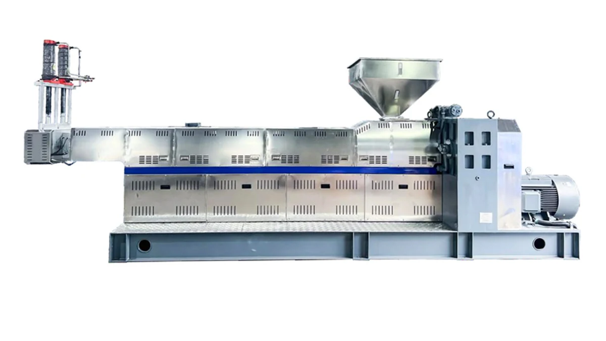
Feed zone — the first section after the hopper opening. Channel depth here is at its maximum. The job is solid conveying: grabbing pellets or powder, compacting them, and moving them forward. If channel depth in the feed zone is too shallow for a high-bulk-density material, throughput is starved at the source.
Compression (transition) zone — channel depth decreases progressively as flights taper. Compression melts the material through a combination of conducted heat from the barrel wall and shear heat generated by the mechanical work of compressing the solid bed. The rate of depth change — called the compression rate — must match how quickly the specific polymer transitions from solid to melt.
A fast-melting material like low-density polyethylene paired with a long, slow compression zone wastes barrel length. A slow-melting or heat-sensitive material paired with an aggressive compression zone generates excessive shear heat and degrades before reaching the die.
Metering zone — channel depth is at its minimum and stays constant. The melt arriving here should be fully homogenized; the metering zone’s job is to build consistent pressure and deliver a steady volumetric flow rate to the die.
Channel depth in the metering zone is the primary determinant of output rate and melt pressure consistency. A shallow metering channel generates higher pressure but risks over-shearing; a deep channel increases output potential but demands a fully melted, low-viscosity material.
Essential Screw Terminology: 8 Terms That Define Extrusion Performance
Engineers ordering custom screws often encounter these terms without a clear reference for how each one connects to actual extrusion performance. Here is a working definition of each, with its practical consequence.
Flight — the helical ridge that wraps around the screw root. The flight separates adjacent channel turns and pushes material forward as the screw rotates. Flight height (the distance from root to tip) directly determines channel depth, and flight clearance (the gap between flight tip and barrel wall) affects leakage flow — material that flows backward over the flight rather than forward.
Excessive flight clearance is a common cause of output loss and melt temperature rise in worn screws.
Helix angle — the angle between the flight and a plane perpendicular to the screw axis. For a square-pitch screw, this is approximately 17.7°. A larger helix angle improves solids conveying efficiency but reduces the number of flights in a given barrel length, effectively compressing functional screw length. Modified helix angles appear in specialty designs for powder processing and high-output film lines.
Pitch — the axial distance between corresponding points on adjacent flights. A square-pitch screw has pitch equal to its outer diameter. Pitch and helix angle are mathematically linked; specifying one determines the other for a given diameter.
L/D ratio — total screw length divided by outer diameter. For general thermoplastics extrusion processes, common values in North American practice span a range rather than clustering at exactly two points: 24:1 is widely used, 28:1–30:1 is frequently cited as most common for general-purpose single-screw lines, and 30:1–36:1 has become the industry standard in some application areas (with 32:1 representing a practical ceiling for many general-purpose lines; values approaching 36:1 are typically associated with specialty or devolatilizing applications).
A longer screw provides more residence time for melting and mixing — beneficial for filled compounds and alloys. A shorter screw (20:1 or less) suits simple, clean-melting resins where additional residence time causes degradation rather than improving melt quality. The L/D ratio range of 20:1–36:1 covers the vast majority of thermoplastic extrusion applications; practitioners should confirm the appropriate value for their specific process against current industry references or their screw supplier’s engineering guidance, as specific published sources for this range should be verified directly.[1]
Compression ratio — feed zone channel depth divided by metering zone channel depth. It expresses how much the material is mechanically compressed as it transitions from solid to melt. Compression ratio is discussed in detail in the section below.
Channel depth — the distance from the screw root to the flight tip, measured radially. Feed zone channel depth is sized to the bulk density and particle geometry of the feedstock; metering zone channel depth governs output rate and back-pressure generation. These two values are the numerator and denominator of compression ratio.
Screw root diameter — the diameter of the screw shaft itself, excluding flights. Root diameter increases from the feed zone to the metering zone as channel depth decreases — this is what physically compresses the material. A worn or incorrect root taper produces inconsistent compression and uneven melting across the screw’s length.
Flight clearance — the radial gap between the flight tip and the barrel bore. Standard clearance varies by application and screw diameter; consult your screw supplier or relevant industry guidelines for the value appropriate to your process and confirm with a qualified authority before specifying.[2] As screws wear, flight clearance grows; the resulting leakage flow reduces output efficiency and raises melt temperature through additional shear.
Tracking flight clearance over a screw’s service life is a straightforward way to schedule re-conditioning before output loss becomes visible in product quality.
📝 Not: L/D values above 36:1 are used in devolatilizing extruders or specialty compounding lines, not standard profile or film extrusion processes.
Key Screw Geometry Parameters and What They Control
Compression Ratio by Material Class
Compression ratio is the ratio of feed zone channel depth to metering zone channel depth. It represents how much the material is squeezed as it transitions from solid to melt. Get this wrong and no barrel temperature setting will compensate.
Compression ratios for common material classes reflect general industry practice — actual values must be validated against your specific resin grade, output target, and die design. Documentation from major resin producers such as Dow and LyondellBasell for their specific grades provides a useful starting point; always confirm the recommended compression ratio with your resin supplier’s current processing guide and a qualified screw designer, as published guidance may be updated or vary by grade.[3]
- Low compression (1.5:1–2.5:1): PVC, PVDF, and other heat-sensitive or shear-sensitive materials
- Medium compression (2.5:1–3.5:1): general-purpose polyolefins, ABS, PS
- High compression (3.5:1–4.5:1): nylon, PET, high-viscosity HDPE
Mismatching compression ratio to material is the most common geometric error in extrusion process troubleshooting. High compression on a shear-sensitive material generates excess heat that no barrel temperature setpoint can cancel out — you are adding heat mechanically, and mechanical heat doesn’t respond to a thermocouple.
The most expensive screw design mistake isn’t buying the wrong screw. It’s buying the right screw for the wrong material spec.
Pitch and Helix Angle
Pitch is the axial distance between corresponding points on adjacent flights. A square-pitch screw has a pitch equal to its diameter, producing a helix angle of approximately 17.7°. This is the standard for most thermoplastic extrusion.
Increasing pitch opens the helix angle, which increases solids conveying efficiency but reduces the number of flights in a given barrel length — effectively shortening functional screw length. Decreasing pitch does the opposite. Modified pitch designs appear in twin-screw extruder configurations and specialty single-screw designs for powder processing.
Flight Depth Profile
Channel depth is not just a metering zone spec. Feed zone depth is sized to the bulk density and particle geometry of the feedstock. Pelletized HDPE and ground PTFE powder require entirely different feed zone geometries even at the same barrel diameter. Feed zone depth that’s wrong for the feedstock produces either surging (insufficient feed) or packing problems that stall solids conveying.
Proven Extruder Screw Design Specs for 5 Common Extrusion Processes
Different extrusion processes place fundamentally different demands on screw geometry, even for the same material. The values below reflect general industry practice — validate against your specific resin grade, output target, and die design before finalizing any screw specification.
| Process | Key Screw Requirement | Typical L/D | Compression Ratio |
|---|---|---|---|
| Film blowing (LDPE/LLDPE) | Low melt temperature, high output stability | 24:1–30:1 | 3.0:1–4.0:1 |
| Rigid PVC profile | Low shear, thermal protection | 20:1–24:1 | 1.6:1–2.2:1 |
| Pipe extrusion (HDPE) | High output rate, pressure consistency | 24:1–30:1 | 3.0:1–4.0:1 |
| Compounding (filled/alloyed) | Intensive mixing, distributive + dispersive | 28:1–36:1 | 2.5:1–3.5:1 |
| Wire & cable (PVC/XLPE) | Melt consistency, no gels | 24:1–28:1 | 2.5:1–3.5:1 |
Screw Elements Beyond the Basic Three-Zone Design
A plain three-zone screw handles clean, single-component thermoplastics reasonably well. The moment you add fillers, colorants, impact modifiers, or run a compound with wide viscosity variation, a plain screw becomes a limiting factor on extrusion performance.
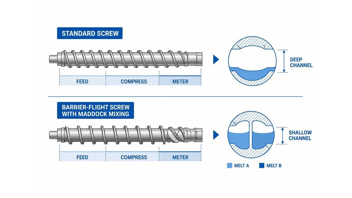
Barrier Flights
A barrier flight is a secondary flight added within the main channel. It physically separates the solid bed from the melt pool as the material transitions through the compression zone. The barrier flight height is set slightly below the primary flight, so melt can flow over it while unmelted solids cannot. The practical result: a narrower solid bed, less unmelted material entering the metering zone, and more consistent melt temperature.
Barrier screws are standard in high-output film and sheet extrusion lines. They generally improve melt temperature uniformity compared to equivalent plain screws at the same output rate — the magnitude of this improvement depends on material, screw speed, and barrel temperature profile and should be confirmed with your equipment supplier. For a more precise estimate for your specific process, polymer processing publications and industry technical bodies provide performance comparisons; practitioners should verify which sources and standards apply to their process with a qualified authority before relying on specific benchmarks.[4]
Maddock Mixing Sections
A Maddock section (also called a Union Carbide mixing section) is a short, intensely-shearing mixing element added at the end of the metering zone. It consists of alternating inlet and outlet flutes separated by lands that the melt must flow over.
The repeated forcing of melt over these lands generates controlled shear — enough to break up agglomerates and disperse colorants, but applied in a short, defined zone rather than throughout the entire screw length.
The trade-off: Maddock sections add pressure drop and increase melt temperature. For materials with tight thermal windows — certain TPEs, for example — that added heat can push the extrusion process outside specification. Industry practice favors Maddock sections for pigmented compounds and mineral-filled resins, but not for unmodified polyolefins running at high screw speeds where melt temperature is already at the upper limit of the processing window.
More mixing is not always better. A Maddock section on the wrong material, or positioned incorrectly relative to the metering zone, adds heat and pressure drop without improving product quality.
Pin Mixers and Static Mixing Elements
Pin mixers use rows of cylindrical pins extending from the screw root into the melt channel, creating distributive mixing without the high shear of a Maddock section. They’re the preferred mixing geometry for glass-fiber-reinforced materials where fiber length preservation matters — high shear from a Maddock section breaks fibers, shortening them and reducing the mechanical properties of the final product.
Static mixers are barrel-end inserts, not screw elements, but they interact directly with screw design: a screw generating good pressure buildup can drive melt through a static mixer effectively; an under-designed metering zone cannot generate the pressure needed for the static mixer to function.
How Screw Geometry Interacts With Material Properties
The screw design doesn’t operate in isolation from the material. Three material properties define what geometry you need.
Melt flow index (MFI). A high-MFI (low-viscosity) material requires a shallower metering channel to restrict flow and help maintain back pressure; these materials generally tolerate or require higher compression ratios because they are easier to pump and less prone to over-shearing.
A low-MFI (high-viscosity) resin requires careful channel depth selection — shallower channels raise shear rates and pressure but risk exceeding motor load limits, so longer metering zones are sometimes used to achieve acceptable output while managing those constraints. Consult your resin supplier’s processing guidelines and confirm the appropriate geometry with a qualified screw designer for your specific grade.
Thermal sensitivity. PVC, PVDF, and certain biopolymers degrade within a narrow temperature window. These materials require low compression ratios, generous channel depths (to reduce shear rate), and often a specifically designed feed zone geometry to avoid prolonged residence time near the barrel wall. Practitioners should consult relevant technical papers on PVC screw design from industry bodies and confirm the applicable guidance with a qualified authority.
Filler loading and particle size. Mineral fillers raise effective melt viscosity and add abrasive wear to the screw surface — the magnitude of this effect depends on filler type, particle size, surface treatment, and matrix viscosity and does not scale in a simple linear fashion with loading level.
A screw designed for unfilled nylon will wear measurably faster running 30% glass-filled nylon — not because the screw design is wrong, but because the surface treatment and flight geometry need to account for abrasion.
For filled materials running in continuous production, flight tip hardening options such as hard chrome or tungsten carbide coatings are commonly considered; verify which treatments are appropriate for your specific material and production conditions with your screw supplier or a relevant industry standard. Consult plastics processing engineering references on wear-resistant screw surface treatments and confirm applicable requirements with a qualified authority.
⚠️ Uyarı: Running a screw designed for unfilled resin on a mineral-filled compound without appropriate surface hardening can reduce screw service life from years to months in high-volume production. Specify the filler loading and particle hardness when ordering any custom screw.
4 Costly Extrusion Problems Caused by Wrong Screw Geometry
Understanding what screw geometry controls makes the failure modes predictable.
Surging — output rate oscillates rather than holding steady. Root causes nearly always trace to either feed zone geometry mismatched to the bulk density of the feedstock, or a compression zone that’s too aggressive, causing solid bed breakup and intermittent melt flow past the solid bed.
Melt temperature too high — screw geometry is generating excessive shear. The fix is not lowering barrel temperatures; it’s reconsidering compression ratio and channel depths.
Barrel heaters add heat, and many extruder designs also incorporate barrel cooling (water-cooled zones) that can remove heat — but mechanical shear heat from an overly aggressive screw geometry is not directly controlled by the barrel temperature controller and must be addressed through screw geometry changes.
Gels and unmelted particles in the final product — the compression zone is too gradual (not enough melting energy) or the screw is running too fast for its L/D ratio, pushing material through before it’s fully melted. Barrier screws and mixing sections solve this; simply raising barrel temperatures often makes it worse for filled or reactive materials.
Degradation streaks — discolored or charred streaks in the extrudate typically indicate dead spots where material stalls and overheats. These are often geometric: poorly designed transition sections or excessively large flight clearances. Or screw-end geometry that leaves a stagnant pool between the screw tip and the die adapter.
The through-line in all of these failures: the screw’s geometry is the first thing to examine, not the last. Processing parameter changes — temperature profiles, screw speed, back pressure — are adjustments within the space the screw geometry allows. If the geometry is wrong for the material, that space may not include the operating point you need.
We have served customers across a wide range of industries and geographies. Industry experience consistently shows that production teams spending months adjusting temperature profiles and screw speeds have almost always been working around a fundamentally misspecified screw geometry. The teams that get it right start by specifying screw design against the material data sheet before the machine is ordered.
For a deeper look at how these principles apply to twin-screw configurations and compounding-specific element selection, the twin screw extruder design guide covers segmented screw geometry in detail.
Screw Geometry Specifications to Request From Any Supplier
When ordering a custom or replacement extruder screw, don’t accept a quote based on diameter and L/D alone. Specify or request documentation for:
- Compression ratio — with feed and metering channel depths stated separately, not as a ratio alone
- Zone length proportions — what percentage of total screw length is allocated to feed, compression, and metering zones
- Flight pitch and helix angle — especially for non-standard materials or high-output applications
- Mixing element type and placement — Maddock, barrier, pin, or none, with position relative to the metering zone
- Surface hardness and treatment — base steel grade, flight tip hardening method, and any corrosion-resistant coatings for filled or reactive compounds
- Material of construction — tool steel grades differ substantially in wear resistance; for abrasive filled materials, ask specifically about bimetallic or tungsten carbide options
A supplier who cannot provide these specifications in writing is supplying a commodity screw, not an engineered one.
The cost difference between a properly specified extrusion screw and a general-purpose unit is generally modest relative to the cost of downstream processing problems — though the exact figure varies by application and screw size. The 15+ years of engineering experience behind our screw design service translates directly into specifications that anticipate those problems before they occur. Industry standards bodies publish guidance on screw specification documentation practices; practitioners should confirm the applicable standard or requirement with the relevant local authority before relying on any specific referenced document.
Taking Extruder Screw Design Knowledge Further: A Practical Checklist
Industry trade publications and technical references on extruder screw design are updated periodically and can be a useful resource; practitioners should verify that any specific guide or standard cited is current and applicable to their process by confirming with the relevant authority before use.
Screw geometry is not a static spec. As production volumes grow, material mix changes, or output rate targets increase, revisiting extrusion screw design is a normal part of process optimization — not a sign that something went wrong the first time.
Before your next screw order, pull the material supplier’s processing data sheet. Look specifically for three parameters:
Melt temperature range. The data sheet will give a recommended processing window, typically expressed as a range in °C. Cross-reference this against the melt temperature your current screw geometry is actually delivering — not the barrel setpoint, which is a different number.
If your measured melt temperature sits at or above the upper end of the recommended range, the screw is generating excess shear heat, and compression ratio or channel depth is the first variable to examine.
Recommended shear rate. Many resin suppliers, particularly for engineering polymers, publish a recommended shear rate range for their materials. Shear rate at the screw channel wall is generally understood to be a function of screw speed, channel depth, and channel width — all geometric parameters — though the precise relationship depends on screw geometry and material rheology; practitioners should confirm applicable calculations and references with a qualified authority rather than relying on any single unverified source.[5] If your operating shear rate exceeds the recommended range, you’re degrading the polymer regardless of what the barrel temperature controller reads.
Melt flow index (MFI) or melt volume rate (MVR). MFI is a proxy for viscosity at a specific temperature and load. As a general principle, lower-MFI (higher-viscosity) resins tend to need different channel geometry than higher-MFI (lower-viscosity) resins to manage motor load and back pressure — but the specific channel depths and compression ratios appropriate for a given MFI value depend on the resin type, screw diameter, and output target.
Confirm the appropriate geometry for your actual grade with your resin supplier’s processing guidelines or a qualified screw designer. Specifying a screw without checking the MFI of the actual grade you’re running is one of the most common sources of mismatch between a screw that “should work” and one that actually performs.
Once you have those three values, compare them against the compression ratio, channel depths, and L/D ratio of your current or proposed screw configuration. The gap between what the data sheet recommends and what your screw geometry produces is where extrusion process problems live. For laboratory extruder configurations, this cross-reference is especially consequential because the L/D ratios are shorter and the margin for error in zone design is tighter.
Engineers with specific questions about cross-referencing data sheet parameters against screw geometry specifications may find resources from polymer processing technical societies a useful starting point for understanding the underlying calculations; however, practitioners should verify any specific standard, publication, or rule with the relevant local authority before applying it, as availability and applicability vary.[6]
Stay Current With Extrusion Screw Design Developments
Extruder screw design is not a settled field. Material suppliers regularly update processing guidelines for new resin grades — particularly as bio-based polymers, recycled-content compounds, and high-filler-loading formulations enter mainstream production. Each new grade potentially requires a revised screw specification.
Several developments are reshaping what “standard” screw design means in current production environments.
First, the growth of post-consumer recycled (PCR) content in polyolefin compounds introduces wider MFI variation lot-to-lot than virgin resin — screws designed for tight virgin-grade specifications may surge or generate inconsistent melt temperatures when PCR content is elevated above what the screw was designed for; the threshold at which this becomes problematic varies by resin system and screw design, so consult your screw supplier when increasing PCR content significantly.
Second, increased mineral filler loadings (calcium carbonate, talc, glass fiber) in cost-reduction programs are accelerating screw wear faster than original service life estimates assumed, making surface hardness specifications more consequential than they were a decade ago. Third, biopolymers such as PLA and PHA have narrow thermal processing windows that demand low-compression, long-transition-zone geometries unlike anything in a general-purpose polyolefin design.
Processing guides and equivalent documentation from major resin producers are updated periodically and remain a useful reference for material-specific screw design parameters; practitioners should confirm that any specific guide is current and obtain the latest version directly from the resin producer, as content and recommendations may change.[7] Following those updates — and cross-referencing them against your installed screw specifications — is the most practical way to stay ahead of process problems before they appear in production.
For ongoing technical guidance on extrusion screw design, the Society of Plastics Engineers’ Extrusion Division[8] publishes technical papers, webinars, and processing guides that cover emerging materials and advanced screw geometries. These are accessible to practitioners at all levels and provide sourced, peer-reviewed benchmarks rather than supplier data sheets alone.
Elinizde bir proje veya teknik şartname mi var? mqextrusion.com ile iletişime geçin — sorularınızı gerçek mühendisler yanıtlayacak.
Sık Sorulan Sorular
What about At a Glance: Key Extruder Screw Design Parameters?
The key extruder screw design parameters are L/D ratio, compression ratio, feed zone depth, metering zone depth, and helix angle. L/D ratios in North American practice span a range rather than clustering at exactly two points: 24:1 is widely used, 28:1–30:1 is frequently cited as most common for general-purpose single-screw lines, and 30:1–36:1 has become the industry standard in some application areas. Compression ratio — the feed channel depth divided by metering channel depth — controls how aggressively the screw works the melt, usually ranging from 2:1 to 4:1 depending on material. Together these parameters set output rate, melt temperature, and mixing quality before the material ever reaches the die.
What Extruder Screw Design Actually Controls: A Practical Overview?
Extruder screw design controls melt temperature, output rate, melt homogeneity, and pressure consistency at the die. The screw geometry determines how solids convey in the feed zone, how the polymer compresses and melts through the transition zone, and how uniformly the melt pumps in the metering zone. A mismatched design forces processors to compensate with barrel temperatures or screw speed, which introduces degradation, surging, or unacceptable variation in wall thickness and mechanical properties in finished parts.
What about 3 Critical Zones Every Extruder Screw Design Must Get Right?
Every single-screw extruder has three zones that must be correctly proportioned: the feed zone, transition zone, and metering zone. The feed zone grips and conveys solid pellets; its channel depth must match the bulk density of the resin. The transition zone melts the polymer progressively — too short and you get unmelts, too long and you overheat. The metering zone pumps a consistent, homogeneous melt to the die. Getting the length ratio and channel depth of all three zones wrong for your specific resin is the root cause of most output instability problems.
Kaynaklar
[1] Principles of Polymer Processing — mahcopipe.com
[2] Clearance hole size for 8-32 screw — facebook.com
[3] Single-screw extrusion performance for LLDPE resin as a… — journals.sagepub.com
[4] How to Optimize Barrel Temperatures for Barrier Screws — mdplastics.com
[5] Average Shear Rates in the Screw Elements of a Corotating… — pmc.ncbi.nlm.nih.gov
[6] Plastik İşleme Eğitimleri (Ekstrüzyon ve Enjeksiyon Kalıplama) — 4spe.org
[7] A Guide to Polyolefin Extrusion Coating — lyondellbasell.com
[8] SPE Extrusion Division announces Screw Design… — plasticsmachinerymanufacturing.com